Rendering in Playstation 1 style in OpenGL
This article outlines the techniques I used to emulate a PS1-style game in OpenGL. I use my own engine for this article, but if you are using one of the popular game engines you will still find the information useful.
Introduction
When creating a brand new Hello World OpenGL project, you will have in front of you a far superior render than the days of Virtual Fighter and Crash Bandicoot. Things have moved on a great deal. Where the developers of old spent effort making their games look as good as possible, we now must spend effort to recreate the simpler aesthetic of these old games.
Contents
Motivation
I am developing an old-school 3D platformer Chaos The Devil.
The idea is to recreate the look and feel of PS1 greats like Crash Bandicoot and Spyro The Dragon.
I aim to do this by applying techniques to create renders which emulate these titles. I am NOT going to restrict myself to the technical limitations of the day.
While researching this topic online, I found a wealth of forum posts and Reddit threads suggesting how to achieve this look. However, implementation proofs of these theories were lacking. This article will therefore highlight the issues I had when implementating these techniques in a real world game dev environment.
Textures
Resolution and Depth
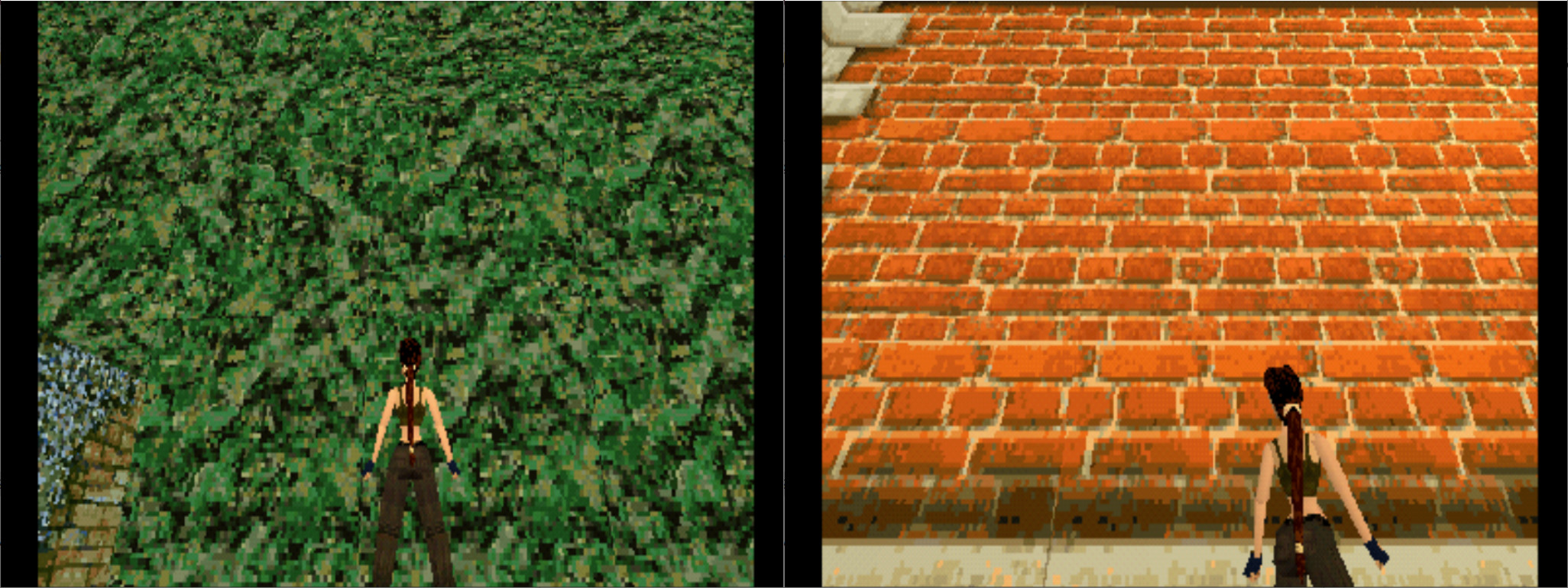
Textures in PS1 games have a distinct look, more like pixel art than true representations.
 |
|---|
| Tomb Raider 1 low texture resolution examples |
Why doesn’t this happen anymore?
OpenGL allows you to plaster any image of your choosing into a graphics scene. Performance-wise, we can really wack up texture sizes these days. The richness in colour of the images we can use as textures is far greater, and we can have full, smooth, transparent sections.
So how do we get it back?
We need to work inside the technical limits of the PS1.
- Mode 4: 4-bit CLUT (16 colors)
- Mode 8: 8-bit CLUT (256 colors)
- Mode 15: 15-bit direct (32,768 colors)
- Mode 24: 24-bit (16,777,216 colors)
Source: PS1 technical specification
From reading whatever I could find about this on the net, it is suggested that the high colour depths were mainly used for static images, and the lower depths were used for in-game polygons.
The approach I took was more artistic than scientific. I studied the textures used in PS1 games and tried to match their look, limiting colour pallets to suit.
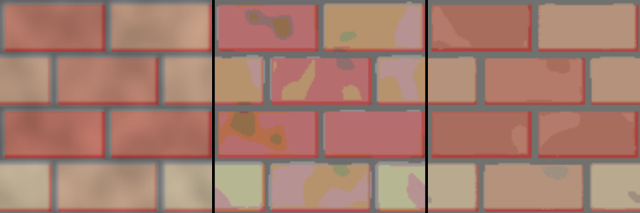
It is often suggested that you could get textures to gain this look in the shader by posterising. However, the PS1 supported colour lookup tables (CLUT), and posterising would actually alter colours.
 |
|---|
| Left: Original source texture. Right: Reduced colours. Centre: Effect of posterising which introduces undesirable colours |
The PS1 was capable of pushing 90k-180k textured polygons a second. However, it was able to push 360k when un-textured see technical Spec. This use of un-textured polygons was often used in conjunction with vertex colouring to increase efficiency. The Crash Bandicoot model was mostly un-textured and, with this in mind, I redesigned my main character to use vertex colouring rather than texture mapping. I also heavily reduced the polygon count to 512 triangles, which was tougher than imagined.
 |
|---|
| Left, hi-poly character coloured with texture mapping. Right, low poly PS1-style character coloured using vertex colouring |
Texture Rendering
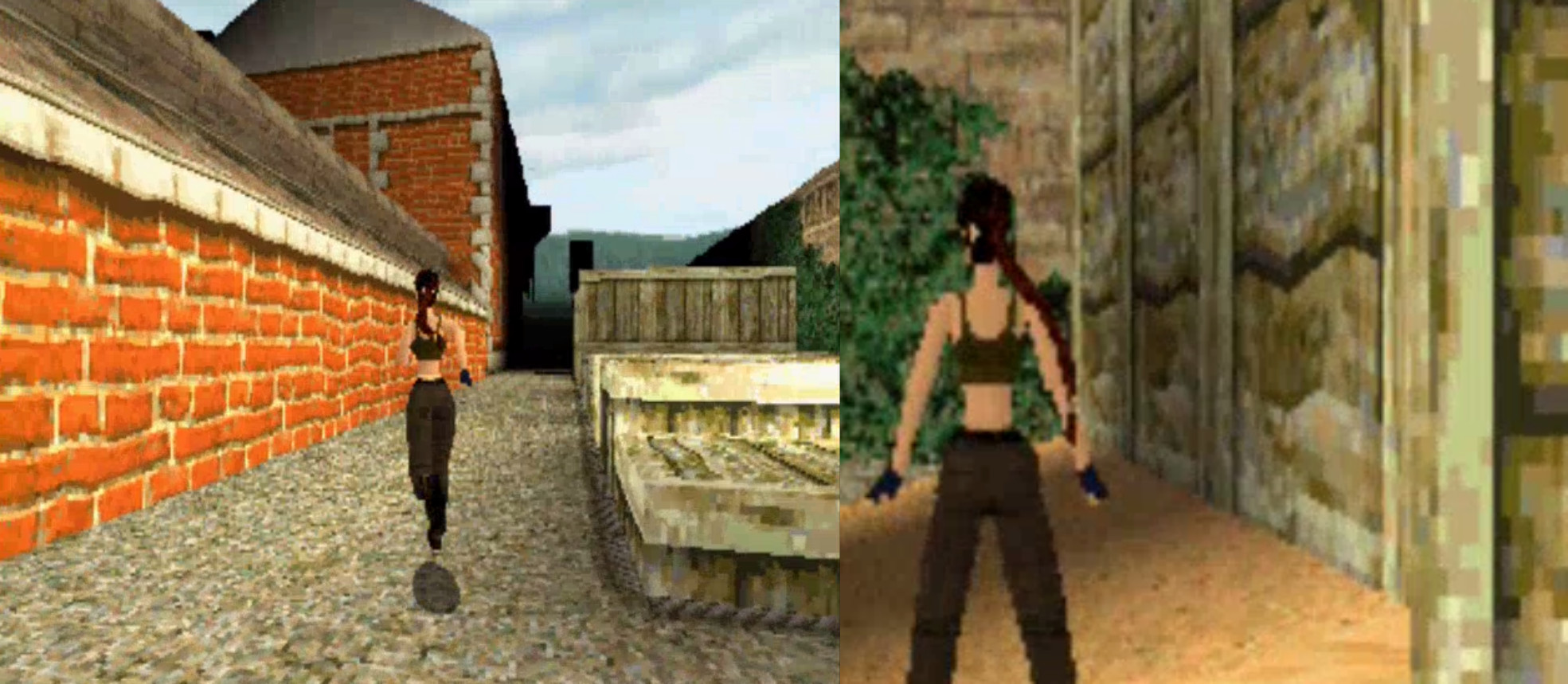
The textures of the PS1 are unmistakable- they are blocky, colourful, sparsely-pixelated and appear to have a personality themselves.
 |
|---|
| Tomb Raider 1 on PS1 showing warped textures |
What’s going on?
Textures being applied to triangles (texture mapping) put in very simple terms work by storing a texture map coordinate for each vertex. These coordinates are then interpolated across the triangle and used to deform the image so that it appears to be on the triangle.
We look up which is the closest pixel to the calculated lookup point and that is the colour chosen for that part of the triangle. Ultimately this is transformed to pixels.
With this approach you would expect a few issues.
-
When the texture is close to the viewer, the pixels can become very large.
-
When the texture is far away, shimmering becomes an issue as the calculation tries to frantically decide which tiny pixel to display from the texture.
-
If the texture is applied to a surface that is not perpendicular to the viewer, it gains a warping effect.
Why doesn’t this happen anymore?
It does, but most example code found on the internet includes settings to mitigate or remove these issues.
-
Textures have interpolation settings in OpenGL.
GL_NEARESTfor example, has the effect of interpolating pixel colour where appropriate, which leads to smoothing of the texture. -
Likewise, shimmering is solved with a combination of this pixel interpolation and the addition of mipmaps. See
GL_GENERATE_MIPMAP -
The way the PS1 handles textures is quite basic- it simply projects the texture onto the polygon (affine). It does not take perspective into account. Perspective correction is now default for OpenGL, which solves the warping.
So how do we get it back?
-
To get that pixelated look back, we need to turn interpolation mode to
GL_LINEARin our textures. -
To gain shimmering textures, we can turn off mipmap generation.
glTexParameteri(GL_TEXTURE_2D, GL_GENERATE_MIPMAP, GL_FALSE); -
To turn off perspective correction on textures, we can use noperspective in our shader.
noperspective vec2 UV;
The largest impact was the change to affine interpolation of textures. This is most noticeable on faces which are near to the camera.
I did encounter an issue I wasn’t expecting. Triangles which had offscreen vertices didn’t work well with affine texturing. This is probably due to the fact that the clip stage alters the geometry, breaking down faces so they fit onscreen. Affine texture mapping goes crazy when this happens.
 |
|---|
| Affine warping effect on polygons which contain offscreen vertices |
I also faced a problem that was much more anticipated. Affine textures are most noticeable when textures contain straight lines. This was an issue that the PS1 developers also had to contend with, so it looks like we are on the right track.
I mitigated both these issues by adding geometry to the scene. I decided to add the extra polygons on load- this way I can more successfully adjust each scene section to work as well as possible. Tesselation could also be done in the shader, however, dynamically changing the tesselation level is noticeable due to the affine texture mapping.
At this point I thought I was done, but then I found another discussion regarding how the PS1 handled clipping. Apparently, the PS1 clipped entire polygons and the developer had to deal with this. This explains why the strange affine warping didn’t occur on the PS1- there are no polygons which contain vertices outside the view.
Apparently, to deal with this, the developer would have to subdivide polygons to minimise the problem and ultimately force the remaining points into view.
As geometry is added to the surface, the affine texture-mapping improves so there is a very visible snap occurring in the polygons which require clipping. This is a curious effect that I witnessed in Tomb Raider.
To recreate this effect, I first tried to use the techniques required to subdivide triangles requiring clipping in the shader and then forcing all vertices into view, and it sort of worked.
The problem with this approach is that some of my meshes are not closed, but next to one another as level blocks, so forcing vertices around made visible holes appear. The other issue was that this approach required substantial changes to my pipeline which I decided was not worth it.
Instead I went with faking the effect, which is well within my brief.
I passed two versions of vec2 UV to the fragment shader, one with perspective correction and the other without for affine. I also passed through a flag which indicated when all vertices of the polygon being rendered were within the view frustrum. If they were, I used the affine UV vector, and if not I used the perspective-corrected vector for UVs.
So when the camera gets close to a polygon there is a visible jump in interpolation quality, which I think gives a good approximation.
 |
|---|
| Left, full affine texture-mapped render. Middle, blue highlights showing polygons which contain offscreen vertices. Right, result of combining perspective texture mapping for polygons with offscreen vertices and affine texture mapping for polygons which reside completely inside view frustrum. |
Polygons
Jittering
Triangles that make up the 3D shapes in a PS1 game, as well as popping (see popping triangles section) appear to dance all over place.
What’s going on?
The PS1 doesn’t support sub-pixel precision when presenting to the frame buffer. This means that when a vertex position is calculated, it snaps to the nearest pixel. The low frame resolutions compound this issue, so the snapping is quite noticeable.
 |
|---|
| Jittering present in Tomb Raider 1 and Croc Legend of the Gobbos |
Why doesn’t this happen anymore?
We can now have subpixel vertex precision and anti-aliasing means even greater precision. This means that our polygons end up exactly where we expect them to be.
So how do we get it back?
Reduce the precision, which can be done in the vertex shader.
//position is post MVP translation of vertex
vec4 to_low_precision(vec4 position,vec2 resolution)
{
	//Perform perspective divide
	vec3 perspective_divide = position.xyz / vec3(position.w);

	//Convert to screenspace coordinates
	vec2 screen_coords = (perspective_divide.xy
							+ vec2(1.0,1.0))
							* vec2(resolution.x,resolution.y)
							* 0.5;

	//Truncate to integer
	vec2 screen_coords_truncated = vec2(int(screen_coords.x),
										int(screen_coords.y));

	//Convert back to clip range -1 to 1
	vec2 reconverted_xy = ((screen_coords_truncated * vec2(2,2))
							 / vec2(resolution.x,resolution.y))
							- vec2(1,1);

	//Construct return value
	vec4 ps1_pos = vec4(reconverted_xy.x,
						reconverted_xy.y,
						perspective_divide.z,
						position.w);

	ps1_pos.xyz = ps1_pos.xyz * vec3(	position.w,
										position.w,
										position.w);

	return ps1_pos;

}
When applying this to a real game context, I noticed a side effect that I haven’t seen discussed elsewhere.
When using this method we are adding a slight offset to the vertex positions, so the shape of the polygon is slightly altered. This works great, as long as all the vertices are aligned exactly.
However, if you have two shapes that are supposed to be together, but with vertices that are not aligned, seams can appear.
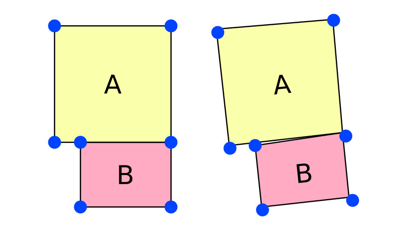 |
|---|
| Left, desired objects rendered together. Right, result of applying a slight rotation with low vertex position precision causing visible gap between objects A and B |
It is easiest to illustrate by example. Referring to the above image, on the left the two squares A and B are together as desired, on the right the two shapes have been rotated slightly and snapped to a grid. As you can see a gap appears between polygon A and B.
The best way to fix this is to have fully closed meshes. No doubt this was the approach used by PS1 games, however I need to keep some flexibility in my authoring as I need to keep the complexity of the project as low as possible.
Some fixes:
- Skybox background which contains similar colours to the main floor, wall and sky works quite well, but limits the level design too much. I want to be able to move between different floor colours during the level.
- Either pragmatically or manually add vertices to the geometry to ensure all vertices match up. This is a bit of a pain to implement.
- Not clearing the colour buffer between draws and accumulating the render. Holes in geometry now are filled with similar colour from previous render. This does quite a good job- most seams are hard to see. The problem is now that the scene cannot rely on clear colours.
I went with the approach of trying to keep my geometry lined up as much as possible, but where this is not possible I fall back to the third approach to cover seams.
 |
|---|
| Left, untreated render showing black sparkles caused by seams appearing due to low vertex precision. Right, result of not clearing colour buffer between frames, making seams harder to see |
After tackling this issue, I noticed the same thing occurring in Tomb Raider 1, which also uses a block system for level building. So, not fixing the issue is also acceptable.
 |
|---|
| Seam between level blocks visible in Tomb Raider 1 on PS1 |
Popping Triangles
When playing an old PS1 game, it is common to see triangles which appear to not quite behave themselves. Sometimes they rest above a surface they should be behind and pop in front and behind one another, which is very distracting.
 |
|---|
| Playstation 1 triangle artifacts present in Crash Bandicoot 1 and Resident Evil 2 |
What’s going on?
When we render something, we are actually performing many calculations which eventually boil down to ascertaining which pixels should have which colour.
So when we want to render a triangle, we work out where on the screen we want it to be using various mathematical transforms- we ascertain an x and a y coordinate and with 3D graphics we also get a z coordinate. This is not an issue with one triangle, but what about if there are two, or more? We need a way to calculate which triangle is on top.
We could just sort by the z value and render in order of farthest to nearest.
This is called the Painters Algorithm and is how the Playstation 1 handles things.
But there is a problem, when triangles intersect or lay in a complex layout, it becomes very tricky to ascertain the draw order of the triangles.
This is exactly what is happening on the PS1, resulting in flickering triangles.
 |
|---|
| Triangle artifacts present in Croc Legend of the Gobbos and Resident Evil 2, caused by z-fighting of polygons |
Why doesn’t this happen anymore?
Pretty much all 3D graphics programs don’t do it this way any more, even Hello World OpenGL applications are more sophisticated.
Nowadays, this issue is fixed with the use of a Depth Buffer. The z-depth value is stored for every pixel and tested against at a per-pixel level.
So how do we get it back?
The simplest way to do this is to turn off the depth buffer and manually draw the triangles sorted by depth order.
However, sacrificing the depth buffer has the knock on effect that all vertex transformations also need to be done on the CPU, so this solution isn’t ideal.
I went another route- by utilising a geometry shader to flatten the triangles, we can create a fake painters algorithm effect.
 |
|---|
| Left, standard colour render of scene. Middle, rendered depth values using depth buffer. Right, rendered depth values with false painters algorithm. |
 |
|---|
| Left, standard render pipeline transforming vertices correctly with depth. Right, false painters algorithm warping polygons and flattening shape |
I made the above illustration to try and show what is happening in the scene. As you can see, from the front the two cubes look identical, but when viewed from the side you can see the false painter algorithm on the right is a slight optical illusion and is actually made up of warped flat polygons.
Some code
Most of the work is done in the geometry shader:
Geometry Shader:
#version 420

layout(triangles) in;
layout(triangle_strip, max_vertices=3) out;

in VertexData
{
	...
} VertexIn[3];

out VertexData
{
	float painter_depth;

	...
} VertexOut;


void main()
{
	//Find best depth for painter algorithm
	float depth = -1.0f;

	for(int i = 0; i < gl_in.length(); i++)
	{
		if((gl_in[i].gl_Position.z >=-gl_in[i].gl_Position.w)
			&&(gl_in[i].gl_Position.z <=gl_in[i].gl_Position.w))
		{
			float z_w = gl_in[i].gl_Position.z / gl_in[i].gl_Position.w;

			if (z_w > depth)
			{
				depth = z_w;
			}
		}
	}

	for(int i = 0; i < gl_in.length(); i++)
	{
		//Copy position
		gl_Position = gl_in[i].gl_Position;

		//Copy attributes
		VertexOut.painter_depth = depth;

		...

		//Create vertex
		EmitVertex();

	}
}
The shader loops through all triangle vertices (transformed into clipspace by the vertex shader) and stores which depth is the furthest from the camera.
It then passes this depth as a vertex attribute to all vertices of the triangle so that it can be used in the fragment shader.
Here is a quick explanation of parts that may be confusing:
if((gl_in[i].gl_Position.z >=-gl_in[i].gl_Position.w)
			&&(gl_in[i].gl_Position.z <=gl_in[i].gl_Position.w))
This ensures that we only process the depth for vertices which are between near and far clip planes. The code inside this decision block performs a divide by w. This w-division is usually performed by OpenGL after the clip stage, however as we are doing it before we need to ensure that w is a valid value. Without this, vertices can end up flipped by depth.
You may also be thinking that it would be better to use the centre of the triangle as its depth, but as the above code sometimes skips vertices which are outside the depth clip ranges it becomes impossible to calculate this average value. We also avoid a divide, which is always a positive.
We could also just alter the depth of the vertices at this point, something like:
	gl_Position.z = depth;
	gl_Position.w = 1.0f;
However, this is using w-divide before the clipping stage and breaks the render pipeline for triangles which have offscreen vertices. It also would cause the perspective interpolation to break which may not be desirable. For example, textures will lose perspective interpolation, which you may not want.
Just to finish off, all that is needed then in the fragment shader is the addition of one line.
Fragment Shader:
gl_FragDepth = (VertexIn.painter_depth + 1) / 2;;
This is simply overriding the fragment’s depth with the one we calculated. We do have to do a bit of maths to convert to the range which OpenGL expects.
One large issue when applying this to a real game was that meshes need to be optimised to work well. My levels are created around a basic block system which warps unit cubes into floor and walls.
 |
|---|
| Left, standard render with wireframe overlay using depth buffer. Right, false painters algorithm showing hidden surface fighting |
This scenario really didn’t work well with the painter algorithm approach. As you can see in the image above, on the left is a render using standard backbuffer, while the render on the right is utilising the fake painters algorithm. You can clearly see the once hidden surfaces clipping to the front, as they are about the same depth as the wall.
To fix this, I needed to be much more mindful of the polygons I am rendering. I altered my code to allow for the manual removal of faces during level authoring. This adds work to level creation workload, but it also leads to faster renders and is absolutely necessary to get the painter algorithm to work.
 |
|---|
| Both left and right show the result of switching between standard depth buffer use and false painters algorithm. Triangle artifacts present in latter technique |
The above animation shows the effect of switching between depth-buffer rendering and rendering with the painter algorithm. You can see triangle artifacts appear with the painters algorithm. These errors can be further reduced with tweaking in authoring, but I kept them very noticeable for this comparison. Note: this image comparison also contains perspective/affine texture switching which is why the textures change. See Textures section for more on this.
Rendering
Frame Resolution
The most obvious development in games is the increase in render resolution. PS1 games had much smaller resolution renders than we are used to these days.
The hardware we use to view the games has also changed. The world has since embraced widescreen aspect ratios and the PS1 aspect ratio was left behind.
But there is more to the PS1 render that needs to be considered. The PS1 scaled down its renders from 8bit to 5bit, which reduces colours. This introduces colour banding. This banding was then mitigated by adding dithering to the render.
 |
|---|
| Examples of aspect ratios for Playstation 1 |
Why doesn’t this happen anymore?
Computers got faster, greater resolutions could be supported and the need for hiding colour banding with dithering was no longer necessary.
So how do we get it back?
We need to render to a lower resolution than the screen that we will be presenting on. This is pretty easy to do, simply render to an offscreen render target and then render the result to a quad shape, which transforms to preserve correct aspect ratio based on window scale.
Resolution technical spec for PS1:
Progressive: 256×224 to 640×240 pixels
Interlaced: 256×448 to 640×480 pixels
To transform the quad that the offscreen game is rendered to, I altered the orthographic camera settings.
I have included the code I used to do this. My engine uses Lua as its scripting engine, but should be pretty simple to follow and port to whatever language you like.
if window_x > window_y then

    OrthographicCameraTop:set(1)
    OrthographicCameraBottom:set(-1)

    image_ratio = window_extent_y / render_resolution_y
    image_width_sized = render_resolution_x * image_ratio

    ratio = window_extent_x / image_width_sized

	OrthographicCameraLeft:set(-ratio)
    OrthographicCameraRight:set(ratio)

  else

    OrthographicCameraLeft:set(-1)
    OrthographicCameraRight:set(1)

    image_ratio = window_extent_x / render_resolution_x
    image_height_sized = render_resolution_y * image_ratio

    ratio = window_extent_y / image_height_sized

	OrthographicCameraTop:set(ratio)
    OrthographicCameraBottom:set(-ratio)

  end
 |
|---|
| PS1 style aspect ratio rendered on wide screen, adding black portions to the screen to keep correct ratio |
Obviously, as seen above, this has the effect of adding black bars to the sides when displayed on a widescreen monitor. A massive development bonus here is that once this is set up, you no longer need to worry about supporting different screen sizes. Your game is always rendered to the same resolution, HUD can stay fixed, and you can completely control what is in view.
Framebuffer colour depth
As listed in the technical spec, the PS1 supported dithering. It appears that developers used this to cover colour banding which occurred due to remapping bit depth to 15bit when rendering to screen.
Looking on PS1 emulation fan forums, it looks like people often really dislike the dithering. This entire project aims to remove it. The thing is that on CRT displays the effect was not so noticeable. I therefore decided to implement this, but as I have done with all the PS1 graphics options, I have the setting exposed in a settings file so the user can turn it off if they want.
 |
|---|
| Silent Hill on Playstation 1, showing a dramatic example of dithering use |
To start with, we need to reduce the colour bit depth to 15bit, this is simply done in the fragment shader which renders the finished game render to the presentation screen quad.
Quick bit of maths to work out how to demonstrate conversion from 8-bit to 5-bit colours effects colour data.
28= (8 bits) 256 different colour values
25= (5 bits) 32 different colour values
So we need to posterise to 32 colours
vec4 posterize(vec4 colour)
{
	float gamma = 0.6f;
	float num_colors = 32.0f;

	vec3 colour_out = colour.rgb;
	colour_out = pow(colour_out, vec3(gamma));
	colour_out = colour_out * num_colors;
	colour_out = floor(colour_out);
	colour_out = colour_out / num_colors;
	colour_out = pow(colour_out, vec3(1.0 / gamma));

	return vec4(colour_out,1.0);

}
This gives us colour banding that we may want to try and cover up with dithering. The PS1 performed the dithering itself and I can’t find much info on it, so I am just going to try and make something that looks similar.
Dithering isn’t too complicated to get going. I implemented an ordered dithering with a 8x8 bayermatrix by following the entry on Wikipedia.
I tweaked the numbers a bit to favour a desirable look so that it isn’t too annoying and adds a bit of flavour to the render.
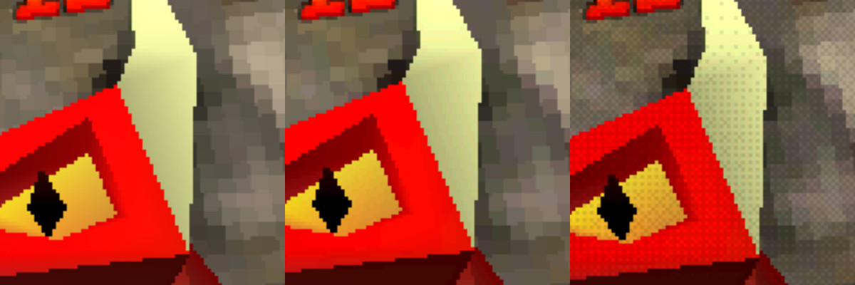 |
|---|
| Left, standard render. Middle, Render colours down scaled to 5 bit producing banding. Right, 5 bit render with dithering applied for smoothing |
Future work
This is where I am going to leave things for this render development pass. However, there are a couple of things I still want to look at if I get time for another pass at the rendering.
- I am not completely happy with the dithering- the results don’t completely match those from PS1 titles.
- I have not explored emulation of CRT monitors- I think this could be fun.
- I didn’t mention loading screens or save menus in this article as I wanted to focus on rendering techniques. But I think emulation of these old-style systems is important for attaining true PS1 style. I have implemented these kinds of things and may blog about it in a follow-up post.
- I think it could be fun to add in CD reading sounds during loading screens- I will probably add this during the audio pass.
Conclusion
Attempting to recreate the PS1 style of rendering is very far-reaching and touches on many different development areas. It amuses me to see the number of techniques usually employed to make a game render become more crisp and shiny but instead used here to make the game jaggy, jitterery, muddy and inaccurate.
The result achieved matches my spec and this is how Chaos The Devil achieves PS1 rendering.
The technique is limiting, especially the false painters algorithm. Separation between coding and art is not really possible- art needs to be created with the rendering limitations in mind.
What next?
Development of Chaos The Devil is full steam ahead and I hope to have a playable demo of the first 8 levels available by the end of the year.
Watch this space.
And if PS1 game dev is your thing, or if you have any questions, follow me on Twitter @JamesRobertHawk and continue to follow my development of Chaos The Devil.
I am going to create more articles like this during the development of the game. I am currently working on an audio pass so if that’s your thing, drop back again soon.
Thanks for your time, happy coding.
JH
Related

